Interaction with peripherals is central to many microcontroller applications. Although the exact capabilities vary from one processor to the other, a set of features known as General Purpose Input/Output (GPIO) is available in most microcontrollers.
| Although the concepts presented here are universal, different versions of MicroPython use variations of the syntax shown in the examples. Check the official documentation for the correct syntax for your device. Popular distributions include standard MicroPython and “Loboris MicroPython” (EE49 uses the latter). |
1. Pin Diagram
Figure 1 shows the connection diagram of the Huzzah32 microcontroller board, an ESP32 microcontroller mounted on a printed circuit board (PCB) with some additional components to support rapid prototyping.
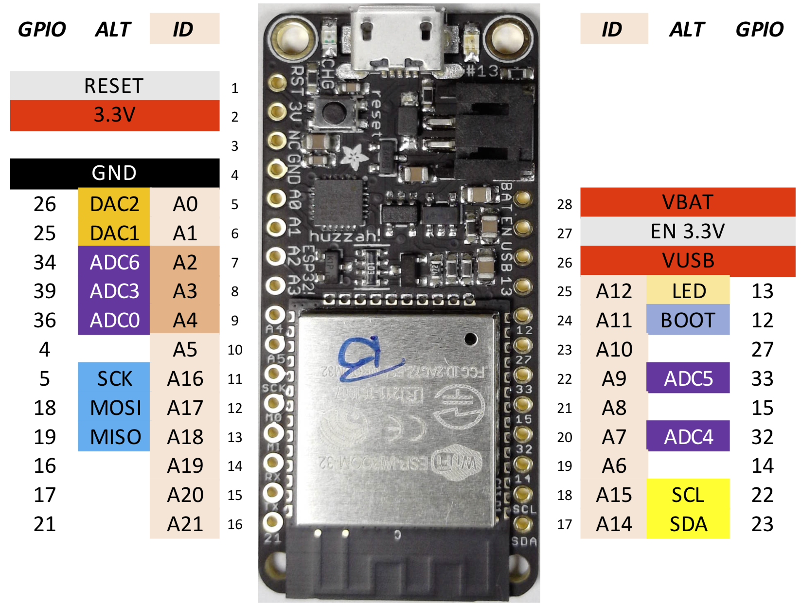
The board features a USB connector for programming, a connector for an optional lithium backup battery enabling autonomous operation, and an array of “pins” (electrical connections) on either side of the board.
Several pins are dedicated to chip power:
| Name | Function |
|---|---|
|
3.3V output from the on-board regulator. Can supply up to 500mA. |
|
Common ground for power and logic. |
|
Positive voltage from USB jack, if connected. ~5V. |
|
Positive voltage from the backup Lipoly battery, if connected. ~3.7V. |
|
3.3V regulator enable pin. Tie to ground to disable. |
|
Reset, tie to |
Power is supplied to the board either through the USB connector, an attached battery, an external 5V supply connected between VUSB and GND, or a 3.3V supply tied to the 3.3V pin. In the latter case pull EN 3.3V low to disable the on-board voltage regulator. VUSB and 3.3V can also function as supplies for connected peripherals when power is supplied though another means (e.g. USB). See the board documentation and schematic diagram for more information.
The remaining pins are for connecting peripherals. Columns ID and ALT show the primary and alternative (for special functions) name of the pin in MicroPython. These names are defined in the board library (Example 1). GPIO is the number of the pin in the official documentation of the ESP32 from the manufacturer.
| Pins with alternative functions can be used for general purpose input/output (e.g. digital, PWM) when the alternative functionality is not required. |
Most pins can be configured by software to perform one of several functions, depending on the need of a particular application. This allows for great flexibility: the same microcontroller can be used in many projects with different peripherals.
| The pins of the ESP32 chip are rated for 3.3V maximum. Exceeding this value may damage the chip. |
2. Digital Signals
The basic unit of information in digital systems is bits. Each bit can assume one of two values, e.g. 0 or 1, or, equivalently True or False. Multiple values are represented by combining several bits. These collections of bits can represent integers, floating point numbers, strings, or more complex data structures.
In the hardware, the state of each bit is represented by voltage. Voltages near 0 (ground) are interpreted as logical 0, voltages near the supply (e.g. 3.3V) as logical 1. This results in great robustness against signal corruption in the presence of interference: unless the value of a digital signal approaches half the supply voltage, it is always correctly interpreted as 0 or 1.
3. Standard Digital Output
All pins A0 … A21 except A2, A3, A4 can be used for digital output.
from machine import Pin   (1)
p = Pin(id, mode=Pin.OUT) (2)
p(0)   (3)
p(1) (4)| 1 | Import Pin library |
| 2 | Declare pin with given id (e.g. A20, defined in board library) as a digital output |
| 3 | Pin p driven low, i.e. 0V |
| 4 | Pin driven high, i.e. VDD (3.3V) |
A5 as standard digital outputfrom board import A0
from machine import Pin
p = Pin(A0, mode=Pin.OUT)Figure 2 shows a simplified diagram of the circuit for a standard digital output used i the microcontroller. It consists of two switches, S1 and S2. The switches are actually transistors, but the difference is not relevant for this explanation. Setting the output to logic 1 closes switch S1, thus connecting the output pin DOUT to the supply, e.g. 3.3V. Similarly, programming the output to 0 opens S1 and closes S2, thus connecting DOUT to ground.

4. Open Drain Output
When configured as open drain, the corresponding pin is pulled low (i.e. tied to GND) when set to 0, and open circuited (i.e. not connected) when set to 1. The circuit is identical to that shown in Figure 2, except switch S1 is never closed.
from machine import Pin
p = Pin(id, mode=Pin.OPEN_DRAIN)
p(0)   # pin driven to 0V
p(1)   # pin open (not driven)
id is the name of the pin, e.g. A0.
Open drain outputs work well for controlling small LEDs (light emitting diodes). Figure 3 shows the characteristic of a red LED. Apart from the higher turn-on voltage of approximately 1.6V @ 295K (22 degrees Celsius), the behavior is similar: for voltages greater than the turn-on, the current and light output increases rapidly.
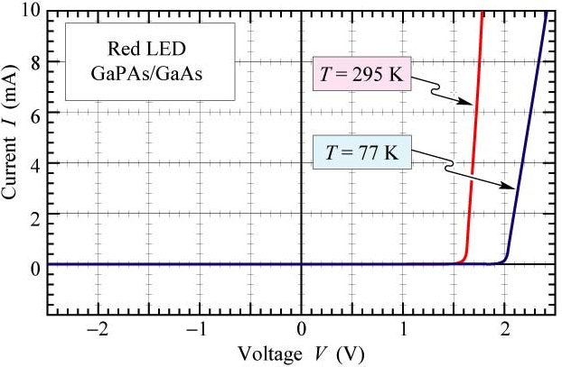
An on-current of 6mA, the maximum recommended for ESP32 GPIO pins, corresponds to just over 1.7V. The diode is very sensitive to this voltage: an error of just 10mV results in a current in excess of 10mA, possibly damaging the ESP32, or the diode being off. Sensitivity to temperature introduces even more variation.
The solution is to control the diode current rather than voltage. This can be accomplished with a resistor in series with the diode, as shown in Figure 4.

The switch S1 represents the open drain driver in the microcontroller. Closing the switch, i.e. setting the output to 0, will turn on the LED. The nominal voltage drop across R1 is approximately 3.3-1.7 = 1.6V. For 6mA current, R1 = 1.6V/6mA = 270Ω. Variation of the diode turn-on voltage (or supply) by up to 160mV cause the current to change by only 10% resulting in a hardly perceptible change of the LED intensity.
Frequently several circuits need to drive the same digital wire at different times. Applications include I2C, where alternatively the master or one of the slaves drives the data bus (SDA).
Figure 5 shows the configuration. Each switch represents the open drain output of a device connected to the bus. When all switched are open, Rup pulls it high and every device observes the bus. To communicate, any of the devices can pull the bus low by closing its switch.
The pull-up resistor must be dimensioned to pull the bus high within the time allocated to transmit one bit. Fast communication consequently requires small values of Rup, especially for long busses with large parasitic capacitance Cbus. In practice, this is limited by the the drive strength of the open drain output and power dissipation.

5. Digital Input
All pins A0 … A21 can be configured as digital inputs.
from machine import Pin
p = Pin(id, mode=Pin.IN)
p()   # 0 if voltage is close to 0V
      # 1 if voltage is close to VDD (3.3V)
id is the name of the pin, e.g. A0.
Optionally, a pull-up R~up$ or pull-down Rdn resistor can be enabled on the pin, eliminating the need for external resistors for circuits that need them. This feature is not available on pins A2, A3, A4.
from machine import Pin
p = Pin(id, mode=Pin.IN, pull=<None|Pin.PULL_UP|Pin.PULL_DOWN>)A21 as input with the internal pull-up resistor enabledfrom board import A21
from machine import Pin
p = Pin(A21, mode=Pin.IN, pull=Pin.PULL_UP)The values of the pull-down and pull-up resistors vary from chip-to-chip and pin-to-pin and for the ESP32 are typically in the range of Rup = 30 … 80 kΩ and Rdn = 17 kΩ (pull-down).
Figure 6 shows a simplified circuit diagram. Switches S1 or S2 are closed if either Pin.PULL_UP or Pin.PULL_DOWN is specified, connecting the corresponding resistor to the input pin DIN. The triangle represents an amplifier that restores correct digital levels (0V or VDD) if a mid-supply input is applied.

Pull-ups and pull-downs are very practical when reading e.g. the state of a switch or button. Figure 7 shows an example. One terminal of the button is connected to a GPIO input, the other to ground. Pressing the button connects DIN to ground, thus establishing a clear logic 0. However, when the button is released, DIN is disconnected and its state therefore undefined. Enabling the pull-up results in DIN = VDD when the button is not pressed, hence establishing a clear logic 1. The pull-down resistor is disabled and not shown in the diagram.

Figure 8 shows a typical waveform when reading a mechanical switch or button. Rather than simply switching on or off, the state changes rapidly between the two states until finally settling. It is caused by the spring effect of the contact. Frequently this is not a problem. For example, when turning lights on or off, short periods of “flicker” are not noticeable.
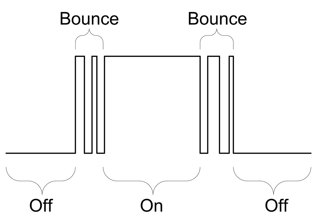
Computers are much faster than humans and detect these changes, typically occurring over a period of a few milliseconds, as individual events. This is problematic for example when counting button presses: the operator presses the button only once, but the machine detects several presses. Imagine a candy vending machine distributing a dozen treats rather than just one.
The simplest solution is to explicitly program the MCU to ignore presses for a short period, e.g. 50ms, after a change is detected. Then only the first change is registered, the “bounce” events in the figure are ignored.
Sample code (fragment):
from board import A8
from machine import Pin
import time

DEBOUNCE_MS = 50    # debounce period in [ms]
button = Pin(A8, mode=Pin.IN, pull=Pin.PULL_UP)

counter = 0         # number of button presses/releases

last_time_ms = 0    # stores last time a change was detected
last_state = button()

while True:
    button_state = button()
    if button_state != last_state:
        # detected a change
        t = time.ticks_ms()   # current time in ms
        if abs(t - last_time_ms) > DEBOUNCE_MS:
            # change detected, take action (e.g. advance counter)
            counter = counter + 1
            last_time_ms = t
            last_state = button_state
        else:
            # bounce event ... ignore
            pass
6. Analog Input (ADC)
The ESP-32 contains two 12-Bit analog-to-digital converter (ADCs). In the Huzzah32 board, one of these converters is available to the user.
The ADC output code for input \(V_{in}\) equals
where \(B\) is the number of bits of the ADC, e.g. 12 for the ESP32.
| “Loboris MicroPython” returns the ADC output scaled to milli-Volts. See the manual for details. Further beware that the ADC in the ESP32 is not very accurate. |
The attn(arg) function is used to set the reference voltage \(V_{ref}\) to one of the values in Table 2.
| Configuration parameter | \(V_{ref}\) |
|---|---|
ADC.ATTN_0DB |
1.1 V |
ADC.ATTN_2_5DB |
1.3 V |
ADC.ATTN_6DB |
1.8 V |
ADC.ATTN_11DB |
3.2 V |
adc0.read() returns the ADC input in milli-Volts).from board import ADC0
from machine import Pin, ADC
adc0 = ADC(Pin(ADC0))
# set full-scale range
adc0.atten(ADC.ATTN_0DB)
# perform conversion
d_out = adc0.read()| The ADC characteristics of the ESP32 vary substantially between parts and suffer from a large offset and poor linearity. See measurement results below. |
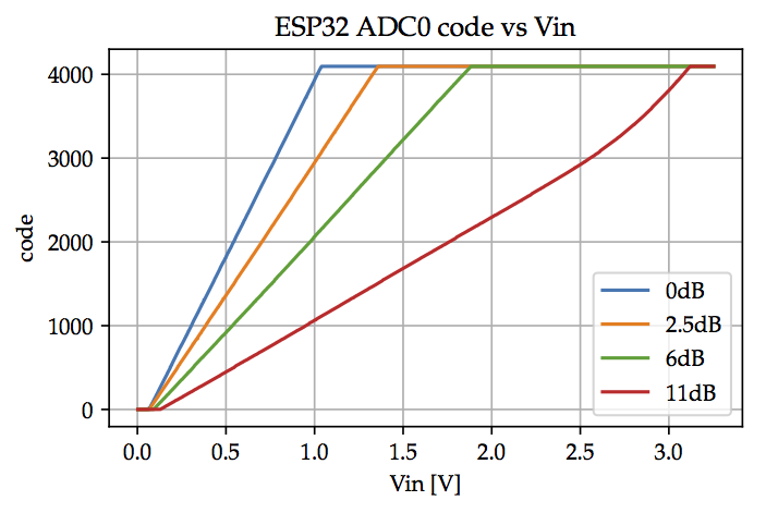
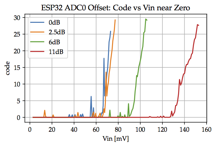
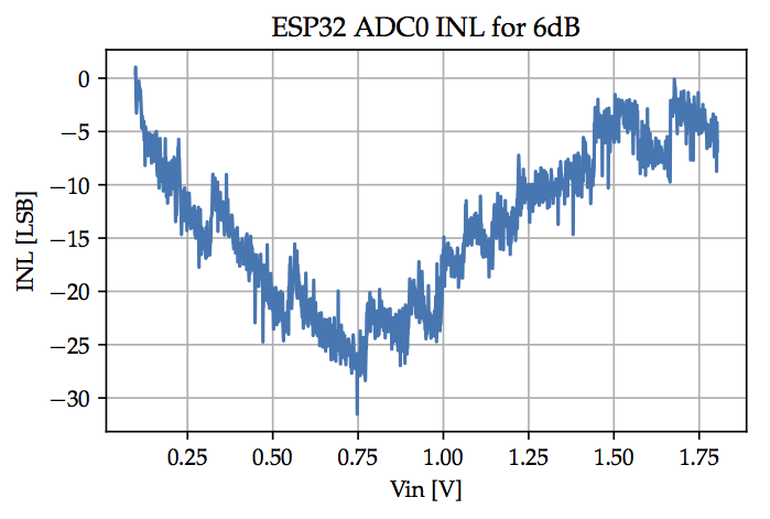
ADC noise (with constant input) is approximately \(\pm25\)LSB (unusually large).
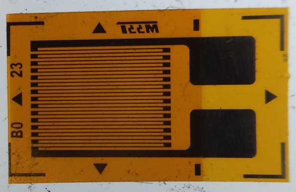
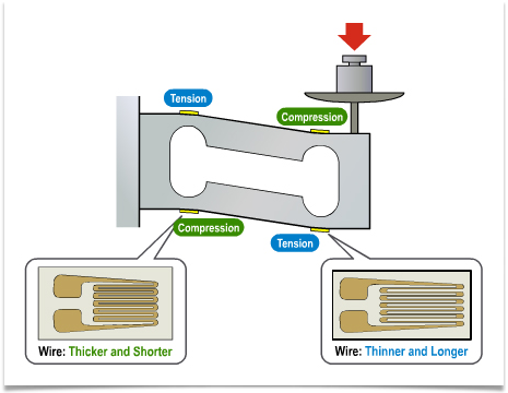
Strain gauges convert mechanical strain \(\epsilon\) to change of electrical resistance.
Strain gauges are used in balances and for structural health monitoring. Figure 12 shows a resistive foil strain gauge. In Figure 13 four strain gauges are attached to a beam, called load-cell, and wired as shown in Figure 14. Resistors R1 to R4 are the strain gauges. Provided the four gauges have the same nominal resistance and gauge factor, the bridge output voltage \(\Delta v\) is proportional to \(\epsilon\).
Since this is typically a small voltage, it is first amplified by a gain \(G\) with an instrumentation amplifier X1 and the output connected to a GPIO pin configured as an analog input used to convert the applied strain (weight) to a digital number.
R5 = R6 = 10kΩ form a voltage divider used to establish a mid-supply reference enabling the setup to measure both positive and negative weights. It is connected to the ground terminal of the instrumentation amplifier (connection not shown in the diagram).

Some microcontrollers have a feature to set the ADC reference to the supply, i.e. Vref = VDD. In this case, the output from the ADC is
independent of the supply voltage VDD. For example, the circuit could be operated from a battery and not be affected by the voltage decrease when the battery ages.
Unfortunately not all microcontroller ADCs offer this feature.
7. Analog Output (DAC)
The DAC reference voltage equals the supply, \(V_{DD}\) (nominally 3.3V). The relation between the code \(D_{in}\) applied to the DAC and the output voltage is
where \(B\) is the number of bits of the DAC, e.g. 8 for the ESP32.
DAC1 output voltage to mid-supply (1.65V)from board import DAC1
from machine import Pin, DAC
dac1 = DAC(Pin(DAC1))
# perform conversion (8-bit DAC)
dac1.write(128)8. PWM
Pulse Width Modulation (PWM) in microcontrollers is a feature to switch a digital output between 0 and 1 at a constant frequency and duty cycle. Applications include blinking or dimming LEDs and motor speed and torque control. Unlike software solutions, once setup a PWM output does not require program intervention, thus freeing the processor to do other things.
The hardware generating the PWM signals consists of timers that set the frequency and channels to set the duty cycle. Four timers are available to set up to four different frequencies.
A0 as PWM output at 20kHz and 30% duty cyclefrom machine import Pin, PWM
from board import A0
p = PWM(Pin(A0), freq=20e3, duty=30, timer=2)
p.freq(30e3) (1)
p.duty(80) (2)| 1 | Change frequency of a PWM output. All channels using the same timer (2 in the example) will be affected. |
| 2 | Change the duty cycle to 80%. |
The timer argument (0 … 3) is optional and defaults to 0. PWM outputs at the same frequency can share a timer, but a different timer is required for each separate frequency. The channel is chosen automatically.
Check the online documentation additional features and examples.
9. Quadrature Decoder
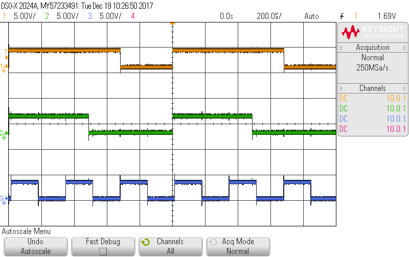
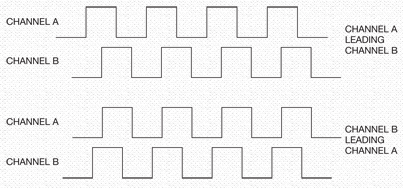
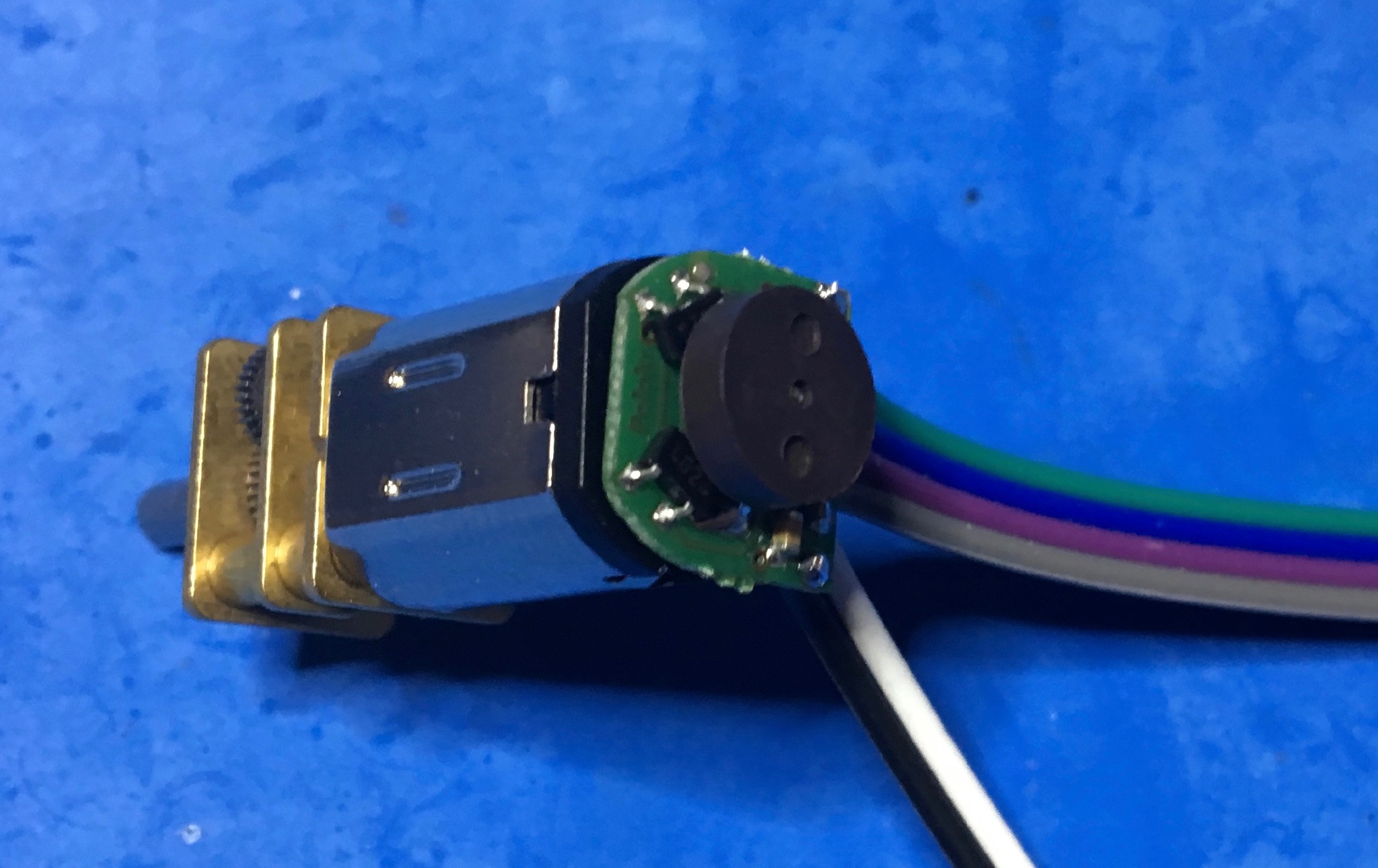
Quadrature signals are used to measure wheel rotation speed. The ESP32 has eight 16-Bit pulse count units, either for quadrature or single input decoders for reading quadrature encoded signals. Figure 16 shows the outputs of a quadrature decoder circuit, typically optical or magnetic sensors attached to a moving shaft, e.g. a motor (Figure 17). Rotation speed or angle is derived from counting the number of pulses. Direction (clock- or counter clockwise) is inferred from the leading channel.
Quadrature input 4-phase counting (counts up or down on raising and falling edges of p1 (channel A) and p2 (channel B)):
from machine import Pin
from machine import DEC
p1 = Pin(id1, mode=Pin.IN, ...)
p2 = Pin(id2, mode=Pin.IN, ...)
dec = DEC(<unit>, p1, p2)
The quadrature decoder peripheral is called DEC.
Single input counting (counts up on raising and falling edge of p):
from machine import Pin
from machine import DEC
p = Pin(id1, mode=Pin.IN, ...)
dec = DEC(<unit>, p1)
<unit> 0 …7 is the pulse count unit number. Choose a different number for each instantiation.
Filtering: Pulse counters feature an optional filter to reject pulses due to bouncing. See the ESP32 API documentation for more information.
dec.filter(value)          # value 0 ... 1023: enable filter with specified value
                           # no-count interval: 12.5*value [ns]
                           # e.g. value=1000 ignores counts for 12.5us
                           # value < 0: disable filter
Available functions:
dec.count()                # returns the current count
dec.count_and_clear()      # returns the current count and resets the counter to 0
dec.clear()                # sets the counter value to 0
dec.pause()                # pauses counting
dec.resume()               # resumes counting
Note: the counters are signed 16-Bit ints and will roll over.
from board import A18, A19, A20, A21
from machine import Pin
from machine import DEC

"""
Quadrature Decoder Demo

Pins A18, A20 generate quadrature input, connected to A19, A21 for counting

Connect A18 --> A19
    and A20 --> A21

Ref: https://github.com/dhylands/upy-examples/blob/master/encoder3.py
"""

# Decoder
quadrature = True   # configure for quadrature or single input counting

if quadrature:
    dec = DEC(0, Pin(A19), Pin(A21))
else:
    dec = DEC(0, Pin(A19))

print("Decoder:", dec)

# Quadrature signal generator

q_idx = 0
q_seq = [0, 1, 3, 2]

qa_out = Pin(A18, mode=Pin.OUT)
qb_out = Pin(A20, mode=Pin.OUT)

def set_out():
    va = (q_seq[q_idx] & 0x02) != 0
    vb = (q_seq[q_idx] & 0x01) != 0
    qa_out.value(va)
    qb_out.value(vb)
    print("{} {}   count ={:4d}".format(
        'X' if va else ' ',
        'X' if vb else ' ',
        dec.count()))

def incr():
    global q_idx
    q_idx = (q_idx+1) % 4
    set_out()

def decr():
    global q_idx
    q_idx = (q_idx-1) % 4
    set_out()

# Demo: count up and down (quadrature==True) or just up (quadrature==False)

dec.clear()
print("      count ={:4d}".format(dec.count()))

for i in range(12):
    incr()
for i in range(24):
    decr()
for i in range(12):
    incr()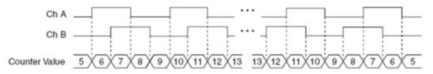
10. Interrupts
10.1. Overview
Polling and interrupts are two different strategies for dealing with events (e.g. a button press).
The following example highlights their differences. Imagine you are expecting an important letter. One option is to regularly check the mailbox. This is called polling. Obviously, this solution is quite inefficient.
Alternatively you could ask the mailman to ring the door bell (or install an electronic circuit on your mailbox that rings the bell when a letter is deposited). Now you are free to go about your business but can rest assured that you will be notified at once when the letter arrives. In microcomputer parlance this is called interrupt. Digital inputs and timers can be configured to interrupt normal program execution when an event occurs and call an interrupt handler, a special function, to service the interrupt. When the handler returns, program execution resumes where it was interrupted.
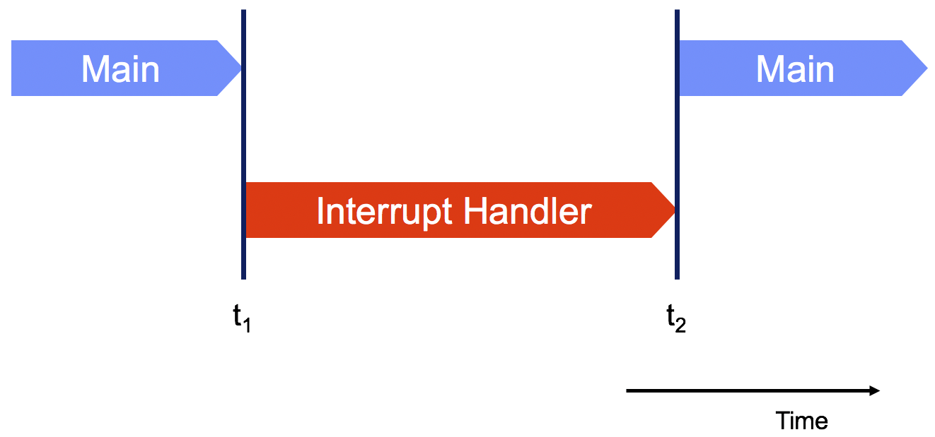
Interrupts are a form of concurrency, and care must be taken not to inadvertently corrupt data. Figure 19 shows program execution during an interrupt. At time t1 interrupt occurs, interrupting running program (Main in the picture). The interrupt handler starts executing, and at time t2 returns control to Main.
The Main program is not aware of it being interrupted and this can cause problems especially with sharing resources. Imagine that Main had just started an I2C but transaction: sent the address and was about to request data from a sensor. If the interrupt handler also uses I2C, it might address a different sensor to read data. When Main resumes execution, it is now that different device on the I2C bus that is addressed. When it asks for data, it gets a response from the wrong device!
There are many solutions for this problem, but unfortunately none trivial. In theory, Main could simply send the I2C address again, but since it is not aware of the interrupt such a scheme is not easy to implement. A simple solution that does work would be to only let Main (or only the Interrupt Handler) access the I2C bus. The Interrupt Handler could set a flag if sensor data needs to be read (and acted on). More complex solutions involve so-called “locks”, which ensure exclusive access to a shared resource. Unfortunately, this raises the danger of “dead locks”, situations where all threads of execution are waiting for the availability of a resource with none able to continue: program execution “freezes”.
Access to I2C is only an example, the same issues apply for any shared resource. Without proper care, interrupts—like other forms of concurrency—can introduce apparently random “bugs” that are difficult to reproduce and diagnose.
Since interrupts handlers stop the currently running program when executing, it is (usually) mandatory that they return control quickly. For example, Main could have started a motor and fails to turn it off after the intended delay because of an interrupt. The MicroPython documentation has tips for writing handlers. General information about speeding up MicroPython execution is available in a presentation by the author of MicroPython, Damien George.
10.2. Digital Inputs
Digital inputs can be configured to call a Python function whenever the value changes.
Important: “Loboris MicroPython” uses the handler parameter on the Pin constructor to configure pin interrupts instead of the irq method. Check the documentation.
from machine import Pin
p = Pin(id, mode=Pin.IN, ...)
p.irq(irq_handler, trigger=<Pin.IRQ_FALLING | Pin.IRQ_RISING>)
trigger may be either Pin.IRQ_FALLING, Pin.IRQ_RISING or Pin.IRQ_FALLING | Pin.IRQ_RISING causing the handler to be called when the input changes from 1 to 0, 0 to 1, or in either direction.
handler is a Python function with one argument (the pin that caused the interrupt).
Specify the name of the irq_handler function without parentheses to pass the function itself, not the result of executing the function!
|
Sample interrupt handler:
def irq_handler(pin):
    print("interrupt handler for pin {} called".format(pin))
Code in interrupt handlers must be short and not allocate memory (e.g. no floating point arithmetic, print statements, or manipulating lists). If any of these features are required or for longer computations, use the schedule function illustrated in Example 10.
from machine import Pin
from board import LED, A21
from micropython import schedule

# connect a button between A21 and GND before running this code

led = Pin(LED, mode=Pin.OUT)

# number of times button was pressed
count = 0   (1)

# extended code (print) called from interrupt
def report(pin):  (2)
    global count
    if pin() == 0:
        print("> pressed {} times".format(count))
    else:
        print("         < released {} times".format(count))

# interrupt handler
def button_irq_handler(button):    (3)
    global count
    if button() == 0: count += 1
    led(1-button())
    schedule(report, button)       (4)

button = Pin(A21, mode=Pin.IN, pull=Pin.PULL_UP)                          (5)
button.irq(button_irq_handler, trigger=Pin.IRQ_FALLING | Pin.IRQ_RISING)

# interrupts occur in the background (concurrent with REPL)
print("Return control to REPL; interrupts continue in background") (6)| 1 | Number of button presses. Global. |
| 2 | Called by interrupt handler. |
| 3 | Interrupt handler. |
| 4 | Interrupt handlers are not permitted to allocate new variables in the heap or do lengthy computation. Use schedule to run such operations at a later time outside the interrupt handler. |
| 5 | Declare the pin and attach the interrupt handler. |
| 6 | Normally the user application (e.g. control robot) would go here. Without control returns to the REPL. Interrupts continue to be handled in the background. |
|
On the ESP32, MicroPython interrupt handlers are always scheduled for later execution by the interpreter. Hence memory allocation (heap) is permitted and the use of MicroPython on other boards (e.g. Pyboard) achieve much lower interrupt latency (few us) but prohibit memory allocation in interrupt handlers. |
Reading button presses with debouncing.
from board import A8
from machine import Pin
from micropython import const
import time

DEBOUNCE_MS = const(50)

class Button:

    def __init__(self, pin, callback=None, falling=True):  (1)
        """ Button with debouncing. Arguments:
        pin: configured pin (incl PULL_UP/DOWN)
        callback: handler, called when button press detected
        falling: detect raising or falling edges
        """
        self.last_time_ms = 0
        self.detected = False  # a button press was detected
        self.cb = callback
        pin.irq(self._irq_cb, pin.IRQ_FALLING if falling else pin.IRQ_RISING)

    def pressed(self):     (2)
        """Return True if button pressed since last call"""
        p = self.detected
        self.detected = False
        return p

    def _irq_cb(self, pin):    (3)
        t = time.ticks_ms()
        diff = t - self.last_time_ms
        if abs(diff) < DEBOUNCE_MS:     (4)
            return
        self.last_time_ms = t
        self.detected = True
        if self.cb: self.cb(pin)   (5)

# sample usage:

def cb(pin):    (6)
    print("Pressed!", pin)

b = Pin(A8, mode=Pin.IN, pull=Pin.PULL_UP)   (7)
butA = Button(b, callback=cb)      (8)

while True:    (9)
time.sleep(0.1)| 1 | Initialize and configure Button |
| 2 | Call this to detect if button was pressed, or use callback handler |
| 3 | Interrupt handler, called each time transition is detected |
| 4 | Ignore interrupts within DEBOUNCE_MS of each other |
| 5 | Call user handler, if defined |
| 6 | User handler, use schedule as needed |
| 7 | Declare pin to which button is connected |
| 8 | Instantiate button instance |
| 9 | User program |
10.3. Timers
Timers are the equivalent of an alarm clock: an interrupt handler is called when the timer expires. Timers can be configured for periodic or one-time (after a specified delay) execution of the handler.
The following code configures a timer for periodic execution:
from machine import Timer

def handler(timer):
    print("timer {} called".format(timer))

t1 = Timer(2)  (1)
t1.init(period=50, t1.PERIODIC, callback=handler)| 1 | Create timer. Four timers are available (argument 0…3). |
See the documentation for additional examples and features.
from machine import Timer
from micropython import schedule
import time

n = 0   (1)
last_time = time.ticks_ms()  (2)

def timer_cb(timer):   (3)
    global n, last_time
    now = time.ticks_ms()
    dt = time.ticks_diff(now, last_time)
    schedule(print_time, [ timer.value(), dt ])
    if n > 20:
        timer.deinit()
    n += 1
    last_time = now

def print_time(args):
    """dt is time since last invocation of handler"""
    print("cb timer.value={:4d}, dt={:4d}".format(*args))

timer = Timer(0)    (4)
timer.init(period=100, mode=Timer.PERIODIC, callback=timer_cb)

while n < 20:
    print(n, last_time, time.ticks_ms())
time.sleep_ms(500)| 1 | Number of times interrupt handler was called. Global. |
| 2 | Another global to measure time between handler invocations. Should equal period. |
| 3 | Timer interrupt callback handler. |
| 4 | Declare timer for 100ms period and attach interrupt callback handler. |
11. Bus Input/Output
Serial busses implement digital communication with other electronic devices using only few wires. The following protocols are supported:
- I2C
-
This protocol is commonly used for sensors and uses just two signals (clock
SCLand dataSDA) to communicate with up to 127 individual devices using device specific addresses. The master (typically microcontroller) initiates the communication by addressing a slave by its unique address, followed by issuing commands (e.g. enter power down mode), reading status registers, or requesting information (such as measurement results). I2C is a “wired OR” bus (see Figure 5) and requires pull-up resistors on the clock and data lines.

- SPI
-
SPI is similar to I2 but uses chip select wires for addressing. It supports higher data rates than I2C and is often used to connect external memories.
- UART
-
The universal asynchronous receiver-transmitter protocol is often used for communication between computers and peripherals such as keyboards and displays.
12. Exercises
Draw the circuit diagram and write the code for reading the status of an on/off switch connected between VDD and input A1 of the microcontroller.
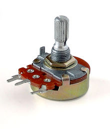
Design a circuit and write the code to measure the position (angle) of a 10kΩ potentiometer.
Write the code to output a 4kHz PWM wave with 50% duty cycle on pin A20. Do not forget to import the correct libraries!
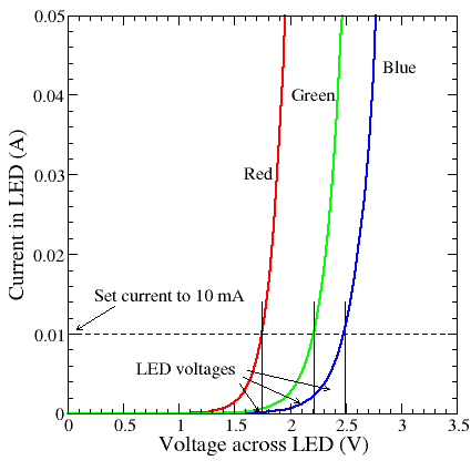
Design a circuit to control a red, green and blue LED from GPIO ports A6, A7, and A8 at 10mA each. Show the schematic with the correct symbols and component values for each circuit element. Complete the code template below to control each LED at 0 … 100% intensity.
def rgb(red, green, blue):
    """ Drive each LED at the specified intensity. Arguments:
    red: intensity of red LED in percent (0 ... 100)
    green: intensity of red LED in percent (0 ... 100)
    blue: intensity of red LED in percent (0 ... 100)
    """
    # your code
    # ...
Use a timer to change the state of a output Pin A20 every 300ms from 0→1 and 1→0, respectively. Show your code.
Calculate the value of the minimum pull-up resistor required for a Fast Mode I2C bus. Fast mode requires the bus to charge from 0V to 70% of VDD in 300ns. Use bus capacitance Cbus=200pF and VDD=3.3V.